
8 月 . 21, 2024 15:58 Back to list
Designing Deep Groove Ball Bearings in SolidWorks for Enhanced Mechanical Performance
Designing Deep Groove Ball Bearings in SolidWorks
Deep groove ball bearings are critical mechanical components widely used in various applications ranging from automotive to industrial machinery. Their design and analysis can significantly influence the performance and efficiency of machines. Utilizing SolidWorks, a powerful 3D CAD software, engineers can create precise models of deep groove ball bearings, allowing for thorough testing and optimization before physical production.
Understanding Deep Groove Ball Bearings
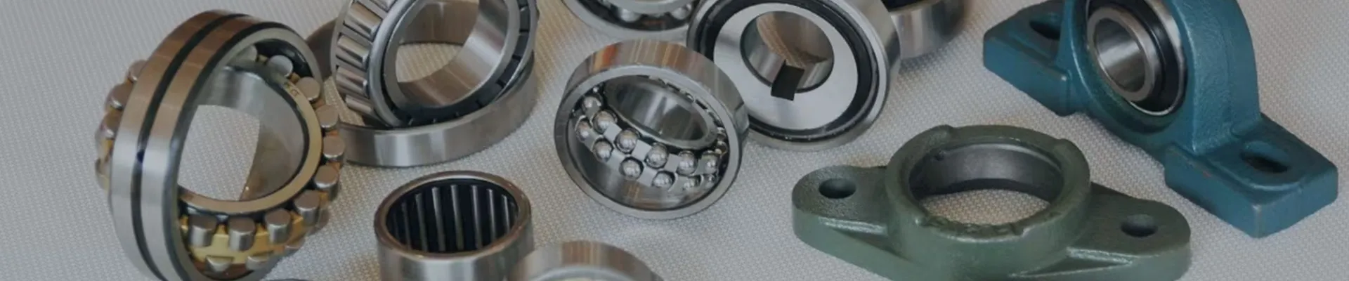
Deep groove ball bearings consist of an inner ring, an outer ring, a cage, and rolling elements—usually steel balls. The design allows them to accommodate both radial and axial loads, making them versatile for different loading conditions. The raceway geometry is crucial to maximize contact area while minimizing friction, leading to higher efficiency and longer service life.
Setting Up SolidWorks for Design
To design a deep groove ball bearing in SolidWorks, begin by launching the application and setting up a new part file. Employ the ‘Sketch’ feature to create the outline of the inner and outer rings on the front plane. Use dimensions that comply with industry standards such as those set by the International Organization for Standardization (ISO) or the American National Standards Institute (ANSI).
When sketching, it's essential to maintain correct proportions between the inner and outer diameters
. Use the ‘Extrude Boss/Base’ feature to give the rings thickness, ensuring that you take into account the loads they will bear in real applications.Adding Features
Once the basic shapes of the rings are complete, you'll need to create the raceways. This can be executed using the ‘Fillet’ or ‘Swept Boss/Base’ options to ensure the raceway profiles are smooth and optimized for reducing stress concentrations. It’s also crucial to create a pocket for the cage and ensure that the rolling elements fit snugly within the assembly.
deep groove ball bearing solidworks

SolidWorks provides tools like ‘Circular Pattern’ to replicate the balls evenly across the bearing space. This feature is vital for creating a symmetrical design, which is essential for balanced load distribution. When positioning rolling elements, be mindful of their size, as it directly influences the bearing’s load rating and performance.
Simulation and Analysis
After modeling, SolidWorks offers robust simulation capabilities that can help validate the design. Utilizing the ‘Simulation’ module, engineers can conduct static and dynamic analyses to evaluate how the bearing performs under various loads and speeds. Key aspects to consider include stress distribution, deformation, and potential points of failure.
The nonlinear static analysis can help determine how the bearing holds up under heavy loads, while the motion analysis can evaluate the effects of rotating speeds on the performance. This evaluation helps in refining the design further, leading to an optimal bearing configuration.
Documentation and Finalization
Once the design and necessary analyses are complete, SolidWorks allows for easy documentation generation. Creating detailed drawings with dimensions, tolerances, and material specifications ensures that the design can be accurately manufactured. Proper documentation is essential for quality control and helps maintain consistent manufacturing standards.
In conclusion, designing deep groove ball bearings in SolidWorks is a systematic process that involves advanced modeling, analysis, and documentation. By leveraging the software’s capabilities, engineers can create highly efficient bearings that meet the rigorous demands of their specific applications. This process not only enhances the product quality but also significantly enhances the development cycle, ultimately leading to increased innovation in mechanical design.
Latest news
-
Unlocking Efficiency with Spherical Roller Bearings
NewsOct.29,2024
-
The Ultimate Guide to Thrust Ball Bearings
NewsOct.29,2024
-
The Power of Thrust Roller Bearings: Engineered for Excellence
NewsOct.29,2024
-
The Power of Deep Groove Ball Bearings for Your Application Needs!
NewsOct.29,2024
-
The Power and Performance of Cylindrical Roller Bearings
NewsOct.29,2024
-
High-Quality Ball Bearing Manufacturing Machines
NewsOct.29,2024