
10 月 . 10, 2024 00:48 Back to list
needle roller thrust bearing size chart
Understanding Needle Roller Thrust Bearing Size Charts
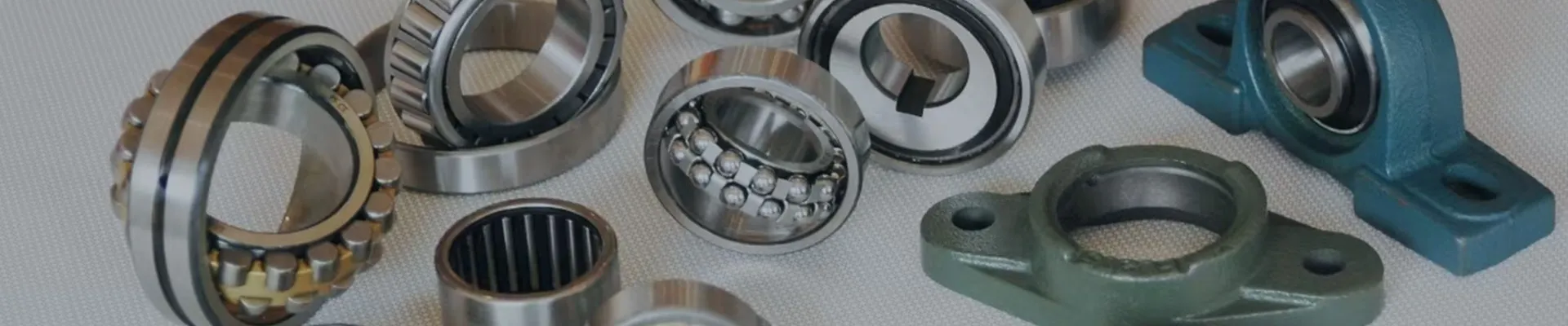
Needle roller thrust bearings are an essential component in many engineering applications, providing support and stabilizing axial loads in various machinery. These bearings are particularly suited for situations where space is limited, given their design that incorporates slender rollers, which allow for a higher load capacity while occupying a smaller overall volume. This article aims to explain the importance of needle roller thrust bearing size charts and provide insights into how to read and utilize these charts effectively.
What is a Needle Roller Thrust Bearing?
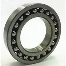
A needle roller thrust bearing consists of a series of cylindrical rollers that are arranged with their axes parallel to each other. These rollers are much longer than their diameter, which is why they are termed needle rollers. This configuration allows the bearing to handle substantial axial loads while minimizing friction. Needle roller thrust bearings are often used in applications such as automotive transmissions, industrial machinery, and other mechanical devices where axial load handling is critical.
The Importance of Size Charts
The size chart for needle roller thrust bearings is a critical tool for engineers and designers. Accurate data on dimensions, load ratings, and corresponding part numbers ensures the correct selection of the bearing for specific applications. The primary factors outlined in a size chart typically include
- Outer Diameter (D) This is the external diameter of the bearing. It is essential for ensuring proper fit within the machine assembly. - Inner Diameter (d) Also referred to as the bore size, this dimension indicates the size of the shaft on which the bearing will be mounted. - Thickness (H) The height or thickness of the bearing is crucial for axial load capacity and overall stability. - Dynamic Load Rating (C) This value indicates the maximum load the bearing can withstand during motion without failure. It is vital for assessing the bearing's performance under working conditions. - Static Load Rating (C0) This rating reflects the maximum load that the bearing can endure while at rest, providing insight into its performance under stationary conditions.
needle roller thrust bearing size chart
How to Read a Needle Roller Thrust Bearing Size Chart
To effectively use a needle roller thrust bearing size chart, one must first identify the application requirements. This includes determining the expected axial loads, speeds, and environmental factors (such as temperature and exposure to contaminants).
Once the requirements are established, follow these steps
1. Identify Required Load Ratings Review the application specifications and identify the dynamic and static load ratings required for the thrust bearing. 2. Locate Suitable Dimensions With the load ratings in mind, check the size chart for bearings that meet or exceed these parameters. It is crucial to ensure that both the outer and inner diameters suit the respective assembly. 3. Consider Compatibility Pay attention to other specifications such as material composition and lubrication type, as these can affect performance and longevity. 4. Verify Performance Factors Some charts also provide additional information about limiting speeds and temperature ranges, which are important for selecting a bearing that will suffice under specific operational conditions.
Conclusion
Needle roller thrust bearings are a vital part of many machines and systems, requiring careful selection based on accurate dimensions and load ratings. Size charts play a significant role in this selection process, providing essential data that engineers can rely on to ensure performance and reliability. By understanding how to read these charts and apply the information effectively, one can significantly enhance the durability and efficiency of mechanical systems. Whether you are an engineer, designer, or technician, having a comprehensive grasp of needle roller thrust bearing size charts will undoubtedly aid in making informed decisions that contribute to the success of your projects.
Latest news
-
Unlocking Efficiency with Spherical Roller Bearings
NewsOct.29,2024
-
The Ultimate Guide to Thrust Ball Bearings
NewsOct.29,2024
-
The Power of Thrust Roller Bearings: Engineered for Excellence
NewsOct.29,2024
-
The Power of Deep Groove Ball Bearings for Your Application Needs!
NewsOct.29,2024
-
The Power and Performance of Cylindrical Roller Bearings
NewsOct.29,2024
-
High-Quality Ball Bearing Manufacturing Machines
NewsOct.29,2024